Modifying Solids
This section teaches you how to modify solids that are inserted on your drawing. You will move, copy, delete, and change the elevation of a solid.
Inserting a Solid
-
Run the Insert Solid: Shape command. The Insert Solid: Shape dialog box will open.
Ribbon: DM Photometrics→Solids→ Insert Solid: Shape
Pulldown Menu: DM Photometrics→Insert Solid: Shape -
Make sure Starting Elevation is set to 0, Ending Elevation is set to 20, and Reflectance is set to 0.5.
-
Press the button. You will be prompted to specify the boundary of the solid.
-
Insert the boundary surrounding the middle tree at the top of the site as shown below. Approximate the circle by drawing a polygon around it.
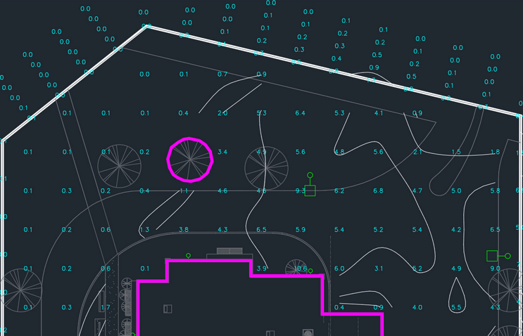
- Run the Calculate command to see the changes in the illuminance levels. Leave the settings as they are and press the button.
Ribbon: DM Photometrics→Calculate→ Calculate
Pulldown Menu: DM Photometrics→Calculate
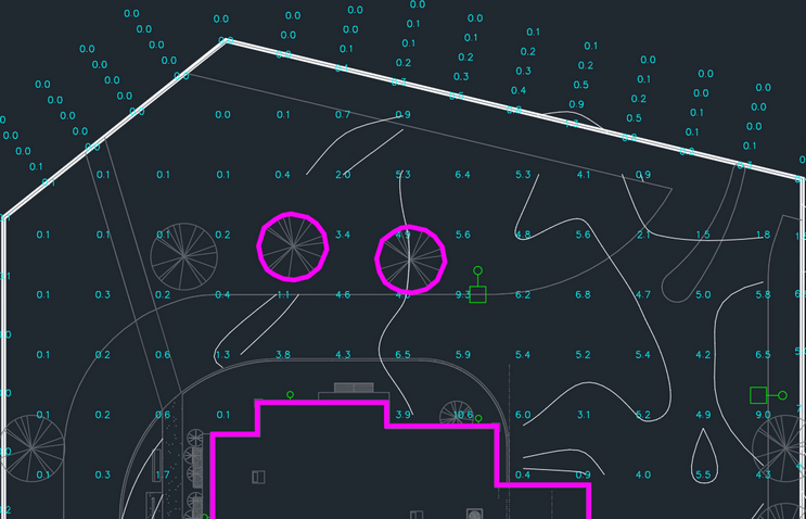
Copying a Solid
Use the standard CAD COPY command to copy the solid to cover the tree to the right.
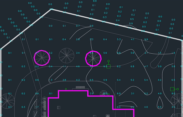
Moving a Solid
Use the standard CAD MOVE command to move the solid on the left to cover the tree to the left.
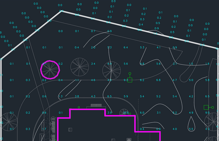
Deleting a Solid
Use the standard CAD ERASE command to delete the solid on the right that is closest to the light fixture.
Changing Settings on a Solid
-
Run the Query command.
Ribbon: DM Photometrics→Query→ Query
Query
Pulldown Menu: DM Photometrics→Query -
Select the solid. The Query Solid dialog box will open. It will display the current settings for the selected solid.
-
Change Ending Elevation to 5.

-
Press the button. The drawing will not change, but the elevation associated with the solid will be updated.
-
Run the Calculate command to see the changes in the illuminance levels. Leave the settings as they are and press the button.
Ribbon: DM Photometrics→Calculate→ Calculate
Pulldown Menu: DM Photometrics→Calculate