Calculate
The Calculate command is used to calculate the illuminance levels on the drawing based upon the light fixtures and solids that have been inserted.
To run photometric calculations, go to
Ribbon: DM Photometrics→Calculate→ ![]() Calculate
Calculate
Pulldown Menu: DM Photometrics→Calculate
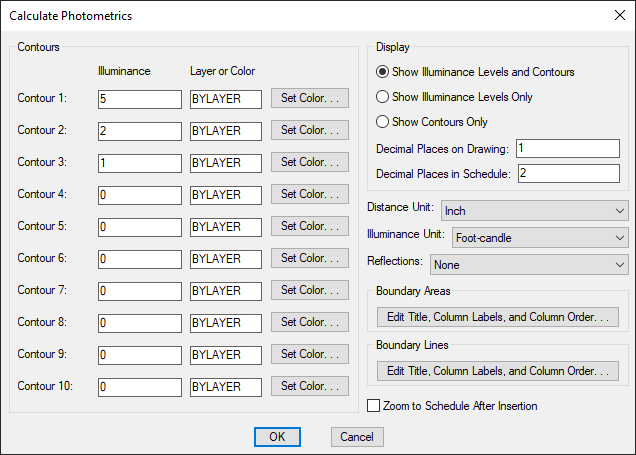
Calculate Photometrics Dialog Box
-
Contour 1 - 10: Illuminance Enter the illuminance level at which to draw contours. Contours set to 0 will not be drawn.
-
Contour 1 - 10: Layer or Color Enter the layer or color of the contour. If the layer specified does not exist on the drawing, it will be created.
- Press this button to open the standard CAD Select Color dialog box.
-
🔘 Show Illuminance Levels and Contours Select this option to show illuminance levels and contours on the drawing. The illuminance levels and contours will be displayed in the calculation area after the calculation is finished.
-
🔘 Show Illuminance Levels Only Select this option to show illuminance levels on the drawing. The illuminance levels will be displayed in the calculation area after the calculation is finished.
-
🔘 Show Contours Only Select this option to show contours on the drawing. The contours will be displayed in the calculation area after the calculation is finished.
-
Decimal Places on Drawing: The number of decimal places to include in the illuminance levels on the drawing.
-
Decimal Places in Schedule: The number of decimal places to include in the illuminance levels on the calculation schedule. If the Decimal Places on Drawing is less than the Decimal Places in Schedule, the smaller Decimal Places on Drawing will be used for the Maximum Illuminance and Minimum Illuminance values in the schedule.
-
Distance Unit: ▾ The base unit for your drawing. See the Base Units and Photometrics Calculations article in the knowledge base for more information about determining the correct Distance Unit ▾ setting for your drawing.
- Inch One unit on the drawing corresponds to one inch. The standard base unit for US architectural drawings.
- Foot One unit on the drawing corresponds to one foot. The standard base unit for US civil drawings.
- Millimeter One unit on the drawing corresponds to one millimeter.
- Centimeter One unit on the drawing corresponds to one centimeter.
- Meter One unit on the drawing corresponds to one meter.
-
Illuminance Unit: ▾ Whether the illuminance levels are displayed in Foot-candle or Lux.
-
Reflections: ▾ Whether the calculation includes reflections from walls.
- None No reflections are included in the calculation. This option is faster, but the calculated values will be slightly lower than reality for calculations near walls.
- Single Light is reflected once during the calculations. This option takes longer, but results in higher values near solids. The light is reflected off of one surface to the ground. Light that hits a second surface is not reflected. For example, light that goes from the light to a wall to the ground is included. Light that goes from the light to the floor to a wall, then back to the floor, is not included.
-
Press these buttons to modify the layout of the photometric schedule for calculation areas and calculation lines on the drawing. See the Edit Calculation Area Schedule Layout and Edit Calculation Line Schedule Layout sections below for more information.
-
☐ Zoom to Schedule After Insertion Whether the display will be moved to the schedule associated with the calculation area.
Edit Calculation Area Schedule Layout
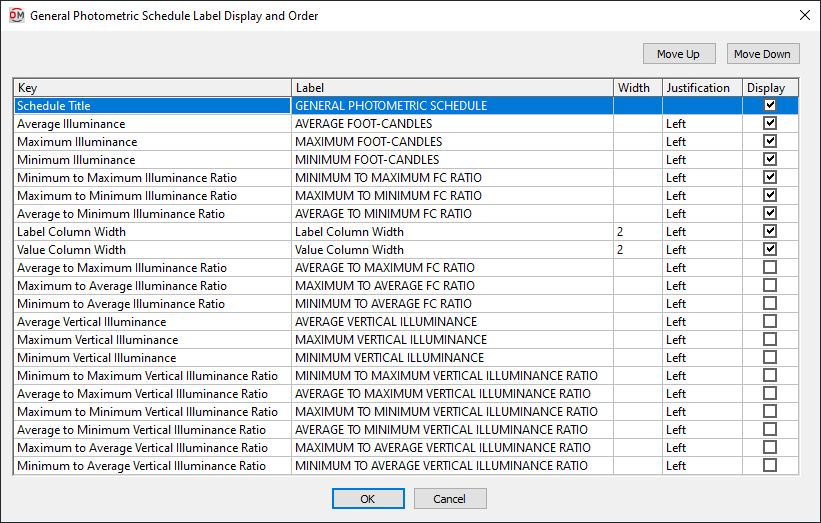
The Calculation Area Schedule Label Display and Order dialog box is used to configure the appearance of the photometric calculation area schedule on the drawing for the current project.
To change the appearance in the master database for future projects, use the Edit Calculation Area Schedule Standards List command.
Grid Columns
-
Key ☰ The identifier for the column, describing what value it will display. The value in this column is fixed and cannot be changed.
-
Label The name that will be displayed for the row.
-
Width The width in inches on the printed drawing.
-
Justification ▾ The justification of the text values in the column. The justification of the title for the schedule and of the column headers are set using the Schedule title justification ▾ options and the Schedule column label justification ▾ option in the Options command.
- Left The text is left-justified.
- Center The text is center-justified.
- Right The text is right-justified.
-
☐ Display Whether the row is shown on the schedule. If this is not checked, the value will not be displayed.
Grid Rows
Each row in the list corresponds to a row in the schedule. The rows in the schedule will be ordered as they are ordered in this dialog box.
-
Move the selected row up in the list.
-
Move the selected row down in the list.
-
Schedule Title The title of the schedule. This row is always listed first and cannot be moved up or down. The Label of this key is the title of the schedule. The Width and ☐ Display values of this key are ignored. The width of the title is based upon the width of the columns in the schedule. The title is always displayed with the schedule.
-
Average Illuminance The average illuminance value in the photometric calculation area.
-
Average to Maximum Illuminance Ratio Equal to .
-
Average to Maximum Vertical Illuminance Ratio Equal to .
-
Average to Minimum Illuminance Ratio Equal to .
-
Average to Minimum Vertical Illuminance Ratio Equal to .
-
Average Vertical Illuminance The average vertical illuminance value in the photometric calculation area.
-
Label Column Width The width of the label column in the schedule.
-
Maximum Illuminance The maximum illuminance value in the photometric calculation area.
-
Maximum to Average Illuminance Ratio Equal to .
-
Maximum to Average Vertical Illuminance Ratio Equal to .
-
Maximum to Minimum Illuminance Ratio Equal to .
-
Maximum to Minimum Vertical Illuminance Ratio Equal to .
-
Maximum Vertical Illuminance The maximum vertical illuminance value in the photometric calculation area.
-
Minimum Illuminance The minimum illuminance value in the photometric calculation area.
-
Minimum to Average Illuminance Ratio Equal to .
-
Minimum to Average Vertical Illuminance Ratio Equal to .
-
Minimum to Maximum Illuminance Ratio Equal to .
-
Minimum to Maximum Vertical Illuminance Ratio Equal to .
-
Minimum Vertical Illuminance The minimum vertical illuminance value in the photometric calculation area.
-
Value Column Width The width of the value column in the schedule.
Edit Calculation Line Schedule Layout
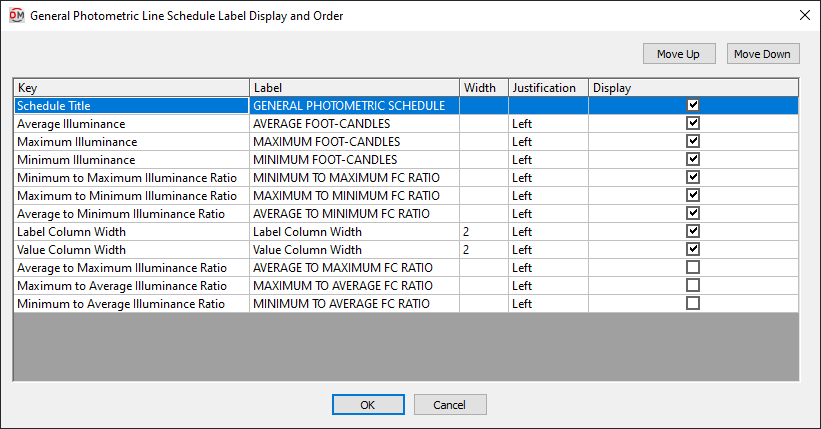
The Calculation Line Schedule Label Display and Order dialog box is used to configure the appearance of the photometric calculation line schedule on the drawing for the current project.
To change the appearance in the master database for future projects, use the Edit Calculation Line Schedule Standards List command.
Grid Columns
-
Key ☰ The identifier for the column, describing what value it will display. The value in this column is fixed and cannot be changed.
-
Label The name that will be displayed for the row.
-
Width The width in inches on the printed drawing.
-
Justification ▾ The justification of the text values in the column. The justification of the title for the schedule and of the column headers are set using the Schedule title justification ▾ options and the Schedule column label justification ▾ option in the Options command.
- Left The text is left-justified.
- Center The text is center-justified.
- Right The text is right-justified.
-
☐ Display Whether the row is shown on the schedule. If this is not checked, the value will not be displayed.
Grid Rows
Each row in the list corresponds to a row in the schedule. The rows in the schedule will be ordered as they are ordered in this dialog box.
-
Move the selected row up in the list.
-
Move the selected row down in the list.
-
Schedule Title The title of the schedule. This row is always listed first and cannot be moved up or down. The Label of this key is the title of the schedule. The Width and ☐ Display values of this key are ignored. The width of the title is based upon the width of the columns in the schedule. The title is always displayed with the schedule.
-
Average Illuminance The average illuminance value along the photometric calculation line, including vertical illuminance levels if they are enabled.
-
Average to Maximum Illuminance Ratio Equal to .
-
Average to Minimum Illuminance Ratio Equal to .
-
Label Column Width The width of the label column in the schedule.
-
Maximum Illuminance The maximum illuminance value along the photometric calculation line, including vertical illuminance levels if they are enabled.
-
Maximum to Average Illuminance Ratio Equal to .
-
Maximum to Minimum Illuminance Ratio Equal to .
-
Minimum Illuminance The minimum illuminance value along the photometric calculation line, including vertical illuminance levels if they are enabled.
-
Minimum to Average Illuminance Ratio Equal to .
-
Minimum to Maximum Illuminance Ratio Equal to .
-
Value Column Width The width of the value column in the schedule.
Calculating Photometrics
After all of the information has been entered, press the button.
If there is only one calculation area or line on the drawing, the illuminance levels will be calculated.
If there is more than one calculation area or line on the drawing, you will be prompted to specify which area or line to calculate.
Select calculation area to calculate / <Calculate all boundaries>:
-
Select calculation areaSelect a point inside an area or along a line to calculate the illuminance levels for just that area or line. -
Calculate all boundariesPress ENTER to calculate the illuminance levels in all areas and lines on the drawing. The illuminance levels and contours will be updated. The values in the corresponding photometric calculation schedules will also be updated.
Schedule title justification: Sets the justification for the schedule title.
Schedule column label justification: Sets the justification for column headings.
There are several options that set the default values for this dialog box. See the Photometric Calculations Options section for more information.