Query
The Query command is used to view and edit the information associated with Design Master Photometrics items inserted on the drawing. You can query light fixtures, calculation areas, and solid objects.
To view and edit an item that is inserted on the drawing, go to
Ribbon: DM Photometrics→Query→ ![]() Query
Query
Pulldown Menu: DM Photometrics→Query
You will be prompted to select an item.
Select photometric item to query:
After you select an item, a dialog box will appear with information about that item. The dialog box that appears depends upon the type of item selected.
Query Light Fixture
When you select a light fixture using the Query command, the Query Light Fixture dialog box will appear.
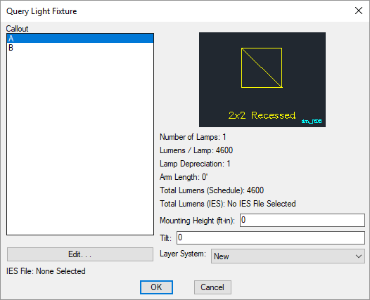
Changes can be made to the light fixture in the same way as when it was inserted. See the Insert Light Fixture section for more information.
-
Number of Lamps: Set using the Number of Lamps field in the Light Fixture Project Schedule command.
-
Lumens / Lamp: Set using the Lumens / Lamp field in the Light Fixture Project Schedule command.
-
Lamp Depreciation: Set using the Lamp Depreciation field in the Light Fixture Project Schedule command.
-
Arm Length: Set using the Arm Length field in the Light Fixture Project Schedule command.
-
Total Lumens (Schedule): Equal to based upon fields set in the Light Fixture Project Schedule command.
-
Total Lumens (IES): The total lumens set in the IES file for the fixture.
If a number is displayed, the light output from the IES file will be scaled based upon .
If Absolute is displayed, the IES file uses absolute photometry. The total lumens for the IES file are not provided. The light output for the fixture will not be scaled based upon the Total Lumens (Schedule) value.
Query Calculation Area
When you select a calculation area using the Query command, one of the following dialog boxes will appear, depending upon the entity you select.
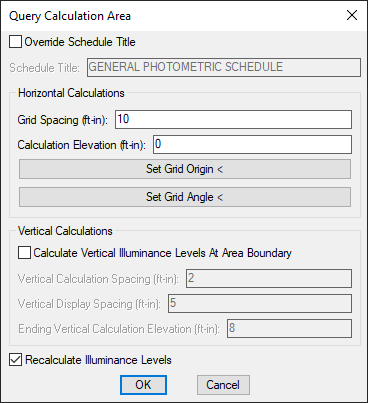
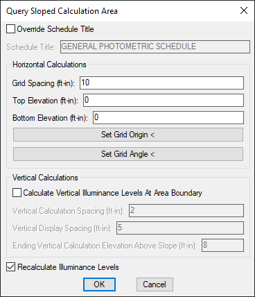
Changes can be made to the calculation area boundary in the same way as when it was inserted. See the Insert Calculation Area and Insert Sloped Calculation Area sections for information about the values in these dialog boxes.
-
Press this button to change the point from which illuminance values are calculated for the selected calculation area. The dialog box will close and you will be prompted to specify a point on the drawing.
Specify illuminance grid origin for calculation area: -
Press this button to change the angle at which illuminance values are calculated for the selected calculation area. The dialog box will close and you will be prompted to specify an angle on the drawing.
Specify illuminance grid angle for calculation area / <0>:Specify two points on the drawing, enter an angle value, or press ENTER to set an angle of 0.
-
☐ Recalculate Illuminance Levels Whether the queried calculation area will be recalculated when you press the button.
Query Calculation Line
When you select a calculation line using the Query command, one of the following dialog boxes will appear, depending upon the entity you select.
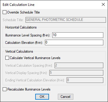
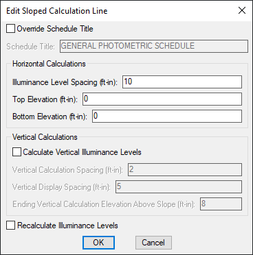
Changes can be made to the calculation line in the same way as when it was inserted. See the Insert Calculation Line and Insert Sloped Calculation Line sections for information about the values in these dialog boxes.
- ☐ Recalculate Illuminance Levels Whether the queried calculation line will be recalculated when you press the button.
Query Solid
When you select a solid using the Query command, the Query Calculation Area dialog box will appear.

See the Common Solids Information section for more information about the values in this dialog box.