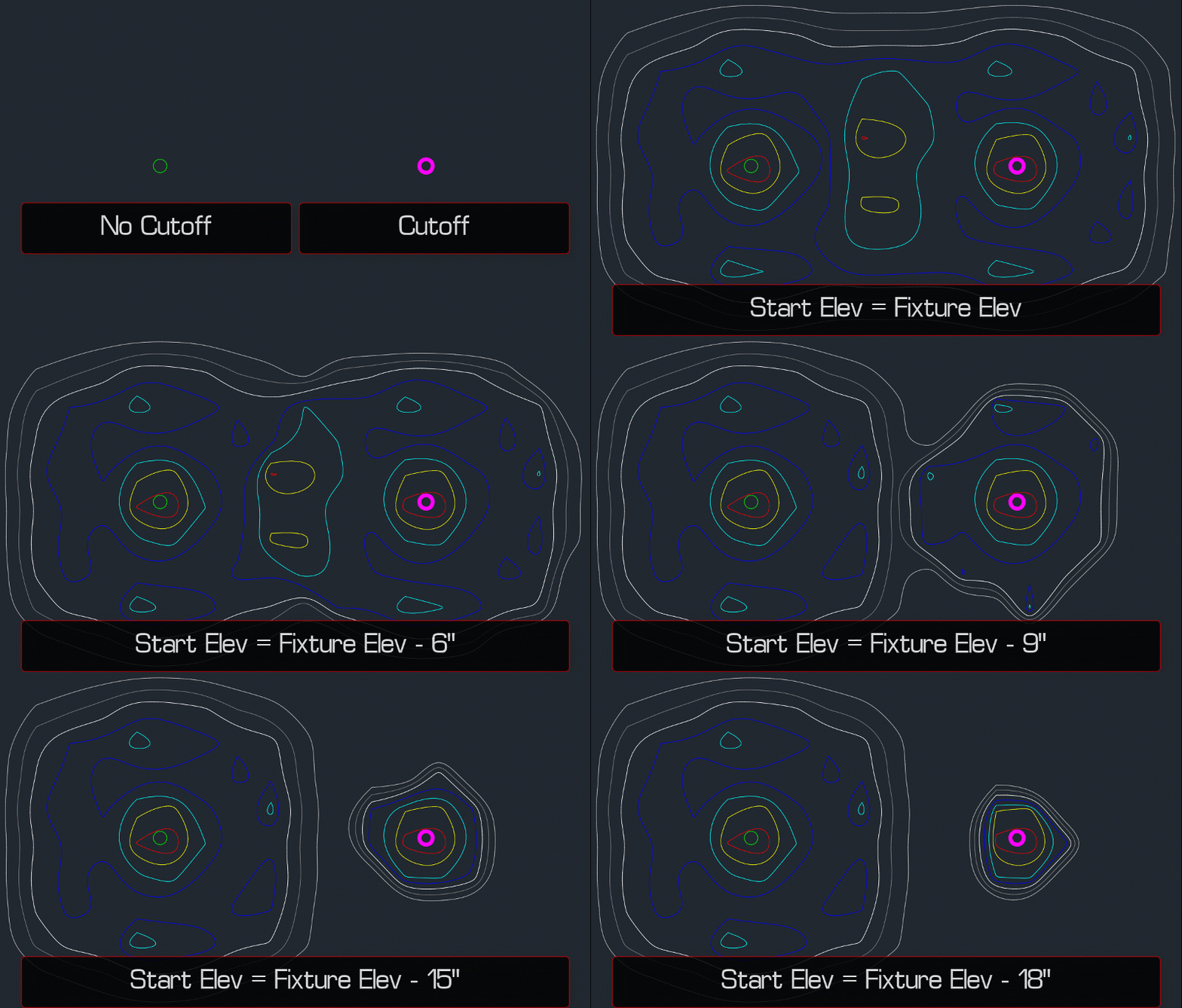
Light Fixture Cutoffs and Shields
Can Design Master Photometrics account for different cutoff configurations on light fixtures?
Design Master Photometrics does not account for cutoffs specifically; however, you can model an approximation using the Insert Solid: Line command.
Some manufacturers may provide IES files for different cutoff configurations. Check for this first, as the IES files they provide will be more accurate than trying to model the cutoff yourself.
-
Create the light fixture and insert it on the drawing.
-
Run the Insert Solid: Line command.
-
Set the Starting Elevation to an elevation below the fixture elevation. How far below will depend upon the type of cutoff you want to model (see image below).
-
Set the Ending Elevation equal to the elevation of the fixture.
noteSetting this elevation higher will not affect light distribution for this fixture, but could affect light distribution for nearby taller fixtures.
-
Press the button.
-
Draw an approximation of the cutoff shape around the fixture (circle/semicircle for circular fixtures, rectangle/straight lines for rectangular fixtures, etc.).
Once the cutoff is drawn, perform a photometric calculation on the area to see if the light distribution is behaving the way you want. If the light distribution is too open or closed, use the Query command to adjust the solid's Starting Elevation, then recalculate. When the light distribution looks correct, you can then use the standard COPY command to place more fixtures with the cutoff on the drawing.
